How to fit a Mortice Lock
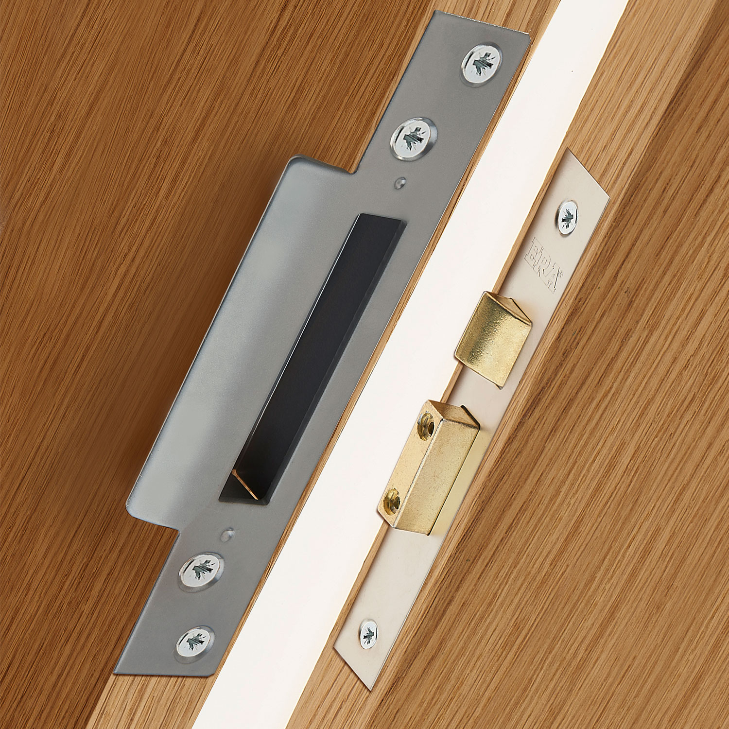
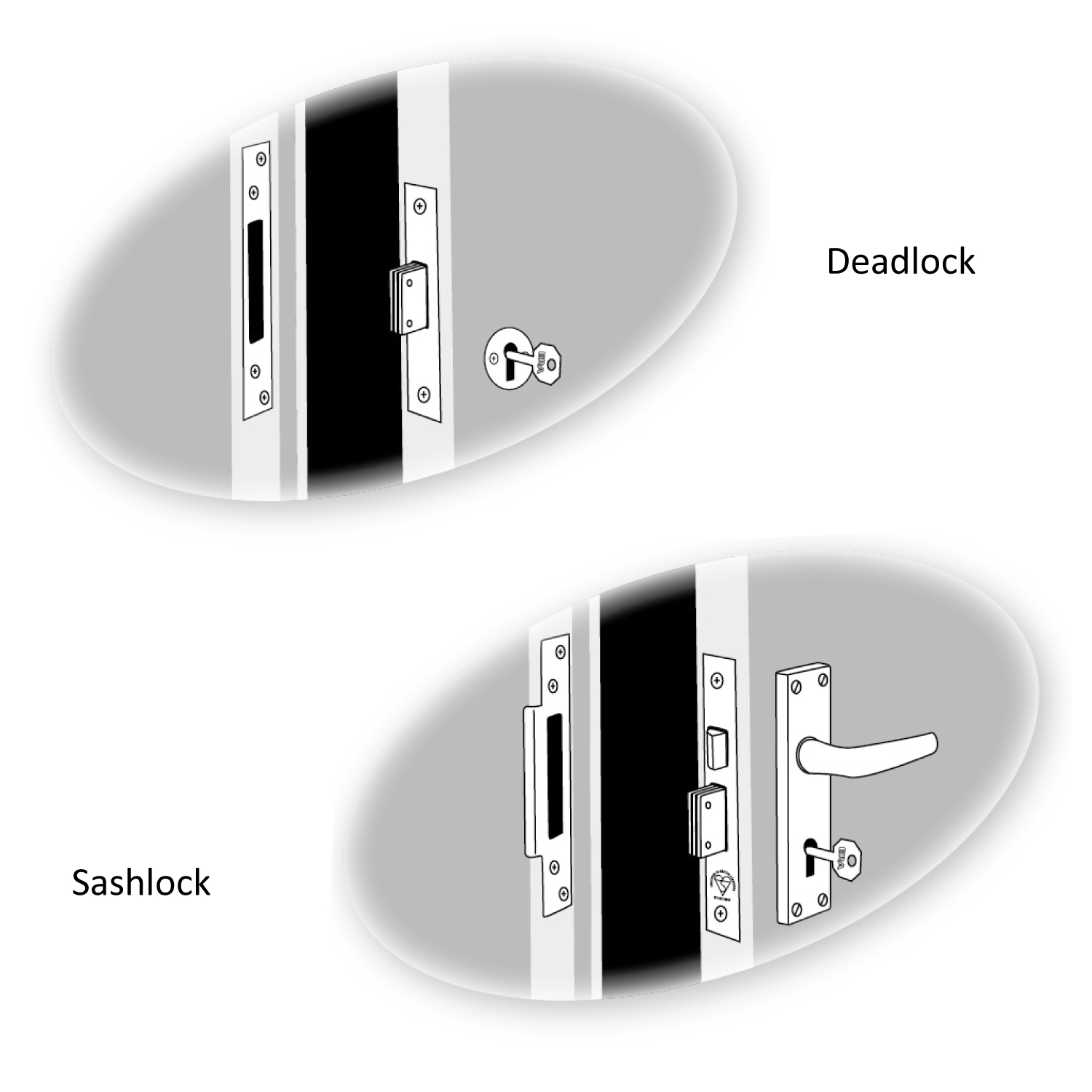
Used in traditional timber doors a mortice lock is embedded in the door for extra strength and provides a locking point in the centre of the door. Available as either a deadlock or sashlock and can have traditional key locking or euro cylinder operation.
Traditional key locking mortice locks use levers and it’s the combination of these levers that give the lock its security. So a 5 lever mortice lock provides greater security than 2 or 3 lever locks that offer lower security.
Many insurance companies specify that as a minimum a BS 3621 five lever mortice lock must be fitted to all external doors. The BS 3621 Kitemark gives assurances that the lock is protected against drilling, picking, cutting or forcing.
The BS 8621 Kitemark has the same protection but offers a method for keyless egress from the house. ERA has a range of British Standard locks to suit most external applications or a choice of non BS 5 lever locks or 3 lever locks for internal applications.
See more about BS 3621, BS 8621 BS 10621 in our how to pick a mortice lock article. Please note this installation guide covers ERA deadlock and sashlock mortice locks. It’s always advisable to refer to the individual manufacturer's instructions for the specific product details.
Jump to section:
How to measure a mortice lock
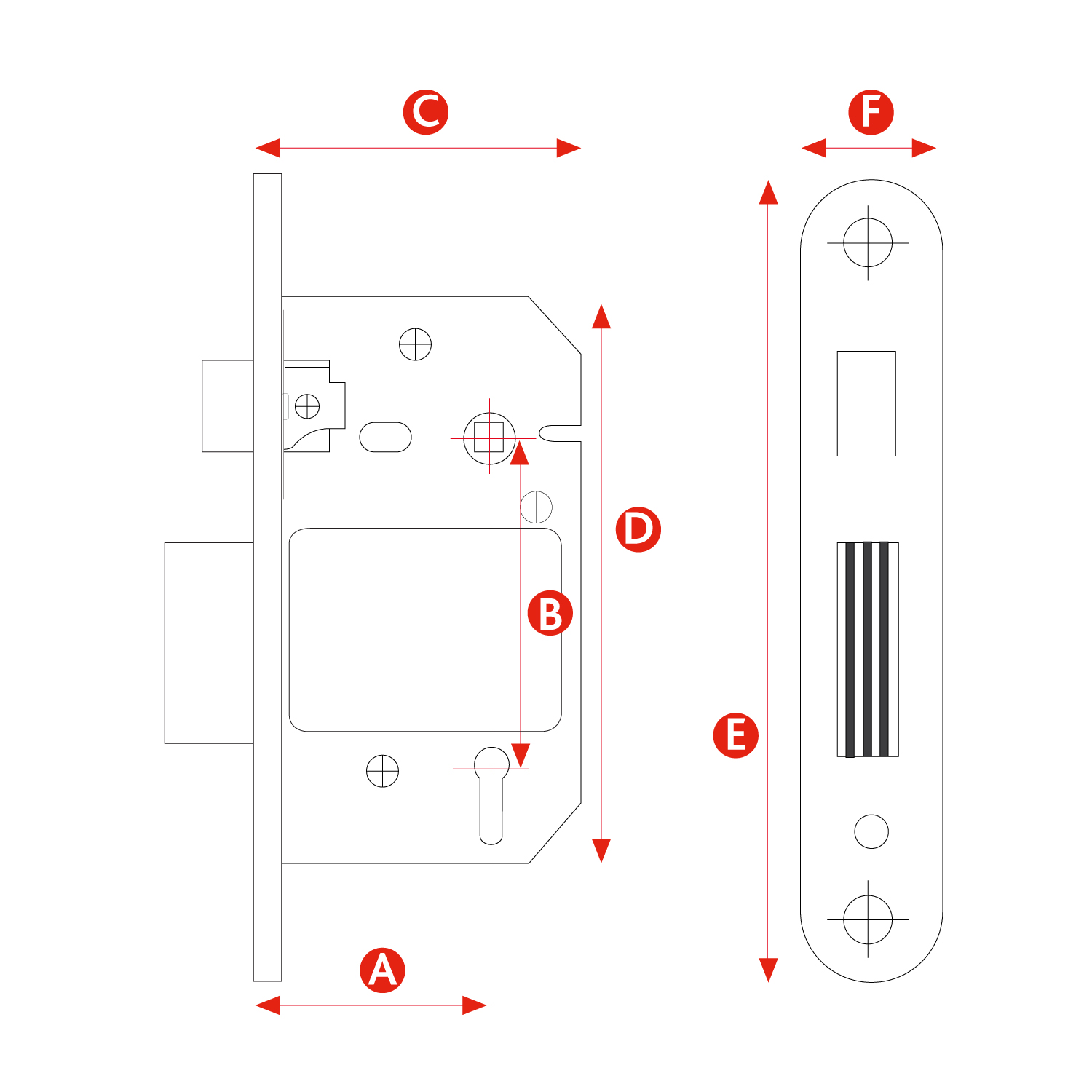
When fitting or replacing a mortice lock there are a few measurements required to ensure that you purchase the correct lock for the application. A drawing of the individual lock (found in the fitting instructions or technical data sheet) is useful for routing information if you are fitting the lock into a new door.
The five key dimensions are shown in the diagram below (sashlock shown):
Dimension A: Backset
Backset is measured from the centre of the keyhole to the edge of the lock. Most backsets are commonly measured at either 44mm (for a 64mm (2½”) lock) and 56mm (for a 76mm (3”) lock). Typically a lock adjacent to a glass panel will be 2½” (44mm) and otherwise 3” (56mm), but you should always measure to be sure.
Dimension B: Centre (Pz)
Measured from the centre of the keyhole/ cylinder to the centre of the follower hole (the square hole the handle spindle passes through). This dimension isn’t required for a deadlock as there is no handle.
Dimension C: Case depth
The depth of the lock when routed into the door, measured from edge to edge. Typically in the UK case depths are generally either 64mm (2½”) and 76mm (3”). However, please check before installing, especially if you are replacing an existing lock.
Dimension D: Case height
The height of the lock case, measured from top to bottom.
Dimension E: Forend (faceplate) length
The overall length of the forend/faceplate (the part that is visible once the lock is fitted). The end of the faceplate may be squared or round.
Dimension F: Forend (faceplate) width
The width of the forend/faceplate (the part that is visible once the lock is fitted). The end of the faceplate may be squared or round.
Removing an existing mortice lock
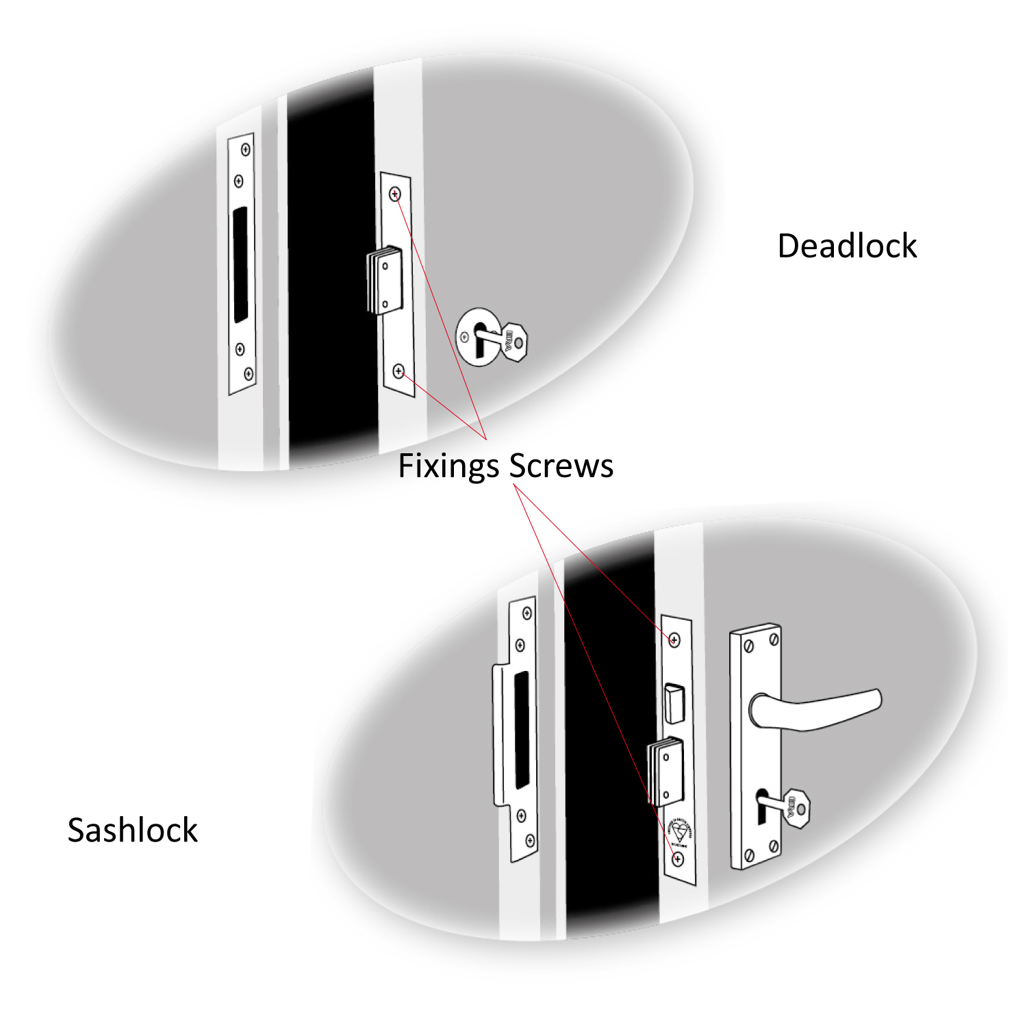
A mortice lock is secured using two screws one at the top and one at the bottom of the lock. These screws are visible on the locking face of the door. Unscrewing these will allow you to remove the lock and forend plate. If you are removing a sashlock, you will also need to remove the handle.
Reversing the sashbolt/latch (if required)
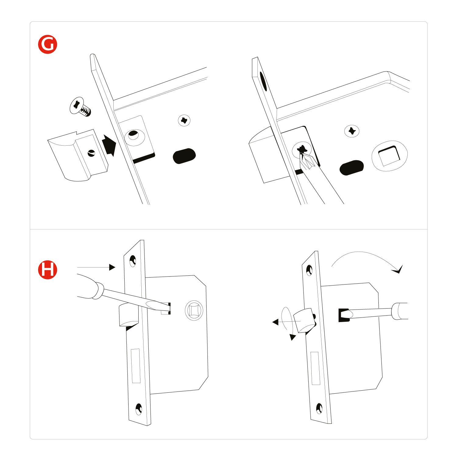
The majority of sashlocks are non-handed, meaning they can be fitted to left or right hung doors. Depending on the handing of the door, you may need to reverse the sashbolt/latch.
The following information details how to do this for ERA mortice locks, however, you should follow the individual manufacturer's guidelines.
Diagram G: 5 lever locks (using a screw in latch bolt)
remove the latch bolt screws, slide out the bolt, revolve through 180º and replace back into the lock. Refit screws tightly.
Diagram H: 2/3 lever locks and Bathroom locks
only you can either pull the latch bolt clear of the forend with a pair of pliers and rotate the bolt head 180º. Or lever the bolt head clear of the forend using a screwdriver. Insert behind the bolt head as shown and rotate the bolt head 180º.
How to fit a mortice lock
Please check that the new mortice lock is suitable for the door before fitting. If replacing an existing lock, please check the dimensions of the new lock mirrors the current one to ensure a good fit. If not, additional routing/ drilling may be required.
To fit a door handle you will need:
- Drill
- Drill bits (please refer to the individual lock fitting instructions for drill bit size)
- Chisel
- Pencil
- Tape Measure / Rule and Square
- Posidrivi Screwdriver
- Mallet
Please note: Although the instructions and illustrations refer to sashlocks, the same procedure applies to deadlocks. It is recommended that suitable pilot holes be drilled before fitting fixing screws (especially in hardwood).
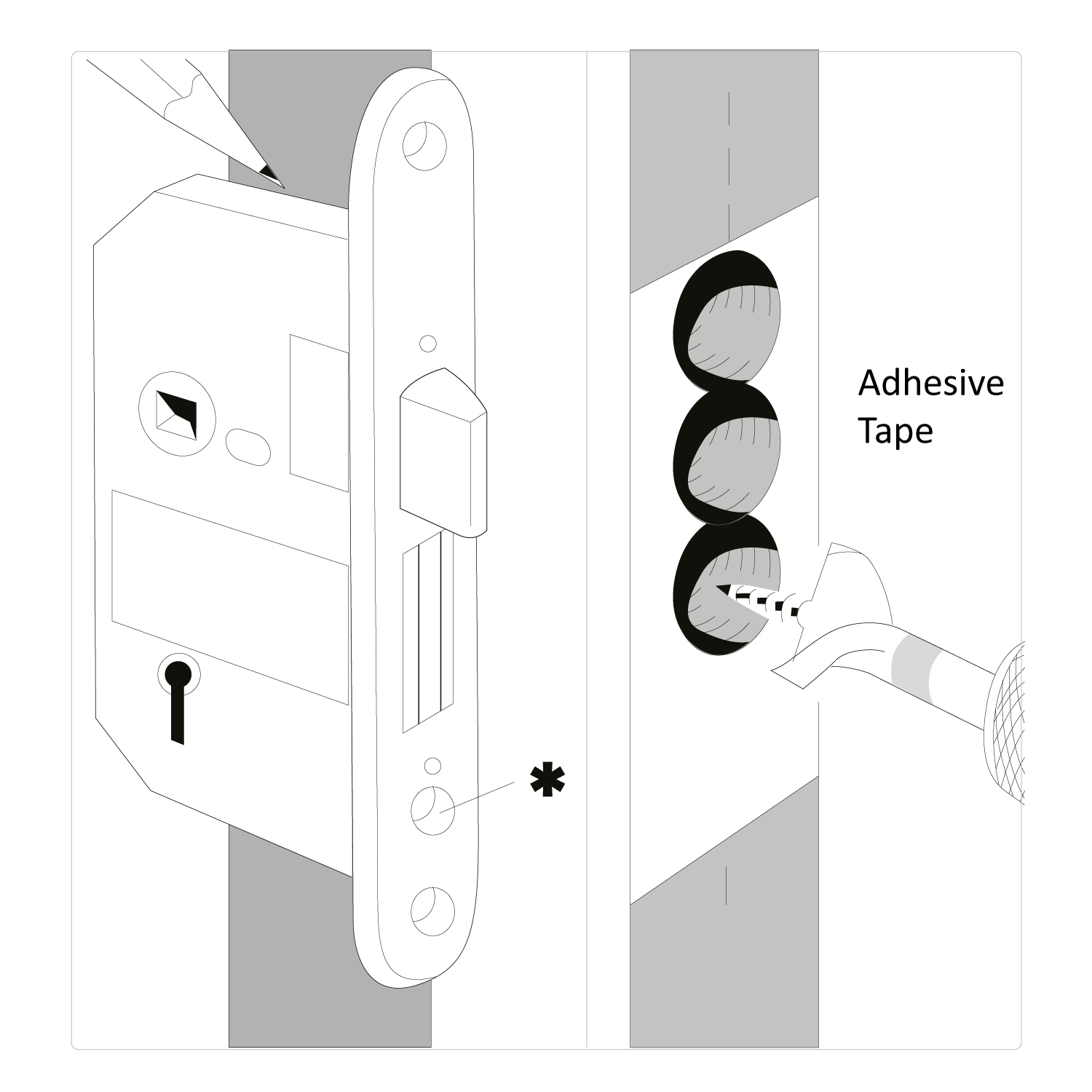
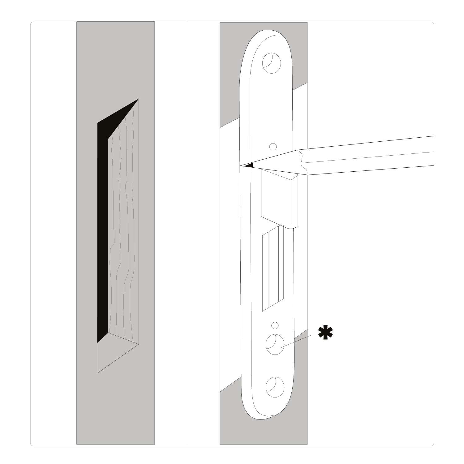
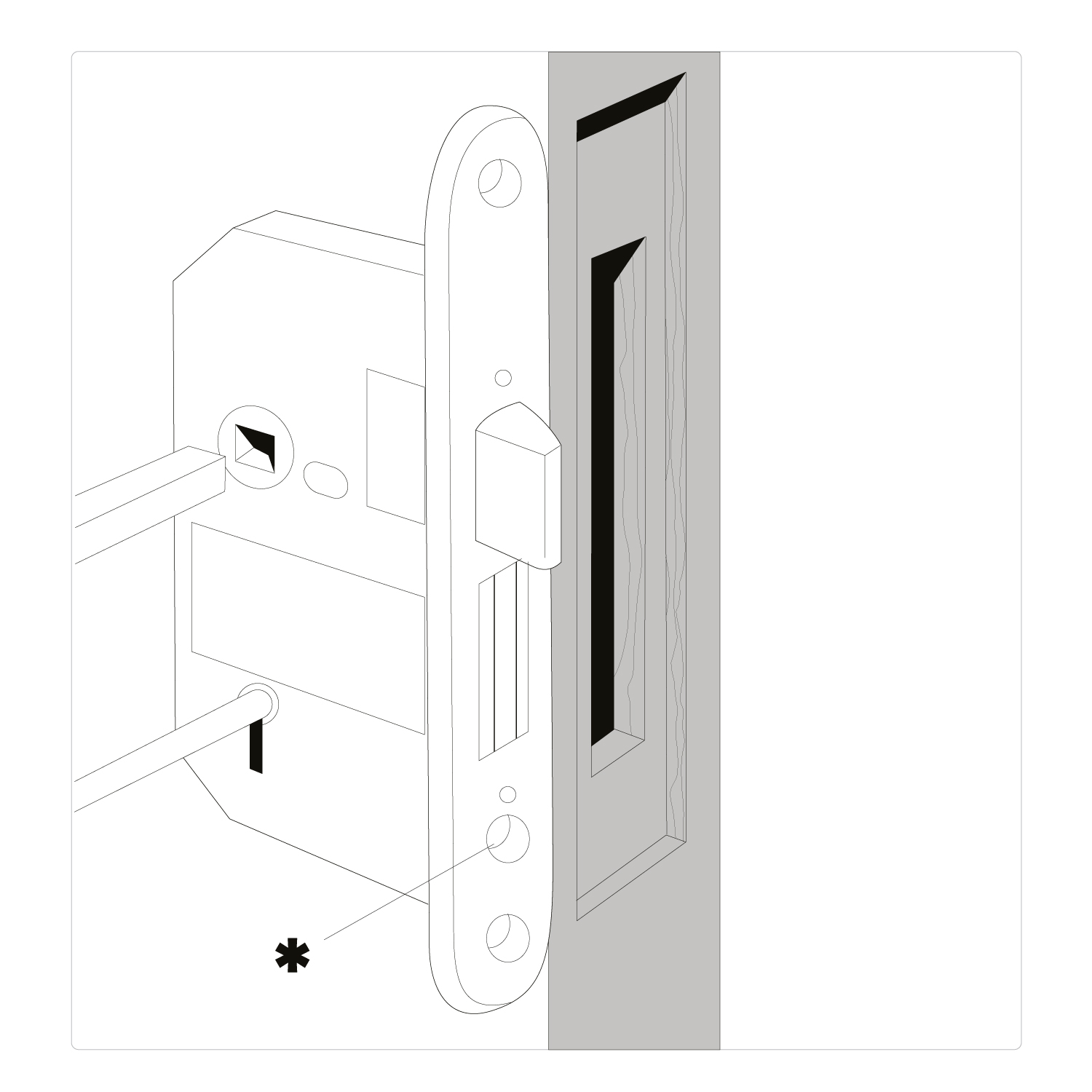
Position the lock body mid-height on the door, or as close as possible. Hold the lock body against the door edge and mark the top and bottom of the lock body on the door edge (avoiding joints of cross members in the door). Please note the hole on the diagram marked * is for use only with cylinder mortice door locks.
Between the two lines, vertically mark the centre (dotted line) and along this vertical line drill a series of overlapping holes to the required lock depth.
To drill to the correct lock depth we recommend applying adhesive tape to the drill bit to the measured lock depth (including forend and faceplate depth).
Carefully chisel out the remaining wood to make a rectangular hole (mortice) to accommodate the lock body.
Insert the lock body into the door and draw around the forend on the door edge (remembering to add the removable faceplate before tracing the outline).
Remove the lock from the door and then chisel the marked recess to accommodate the lock faceplate.
Place the lock into the door and ensure a good fit. The faceplate should be flush with the door edge.
Please note: if you are fitting a sashlock, please check handing. With the lock fitted in the door, check the sashbolt is suitable for your door opening. Gently close the door. The curved edge of the sashbolt (latch) must be facing the door frame, if not, the sashbolt must be reversed (instructions).
Hold the lock against the face of the door ensuring the faceplate is flush with the door edge and in line with the lock recess.
Mark the position of the keyhole (and spindle if applicable), drill and cut holes on both sides of the door for the key (and spindle).
Place the lock into the door making sure that the key (and spindle) pass freely into the lock.
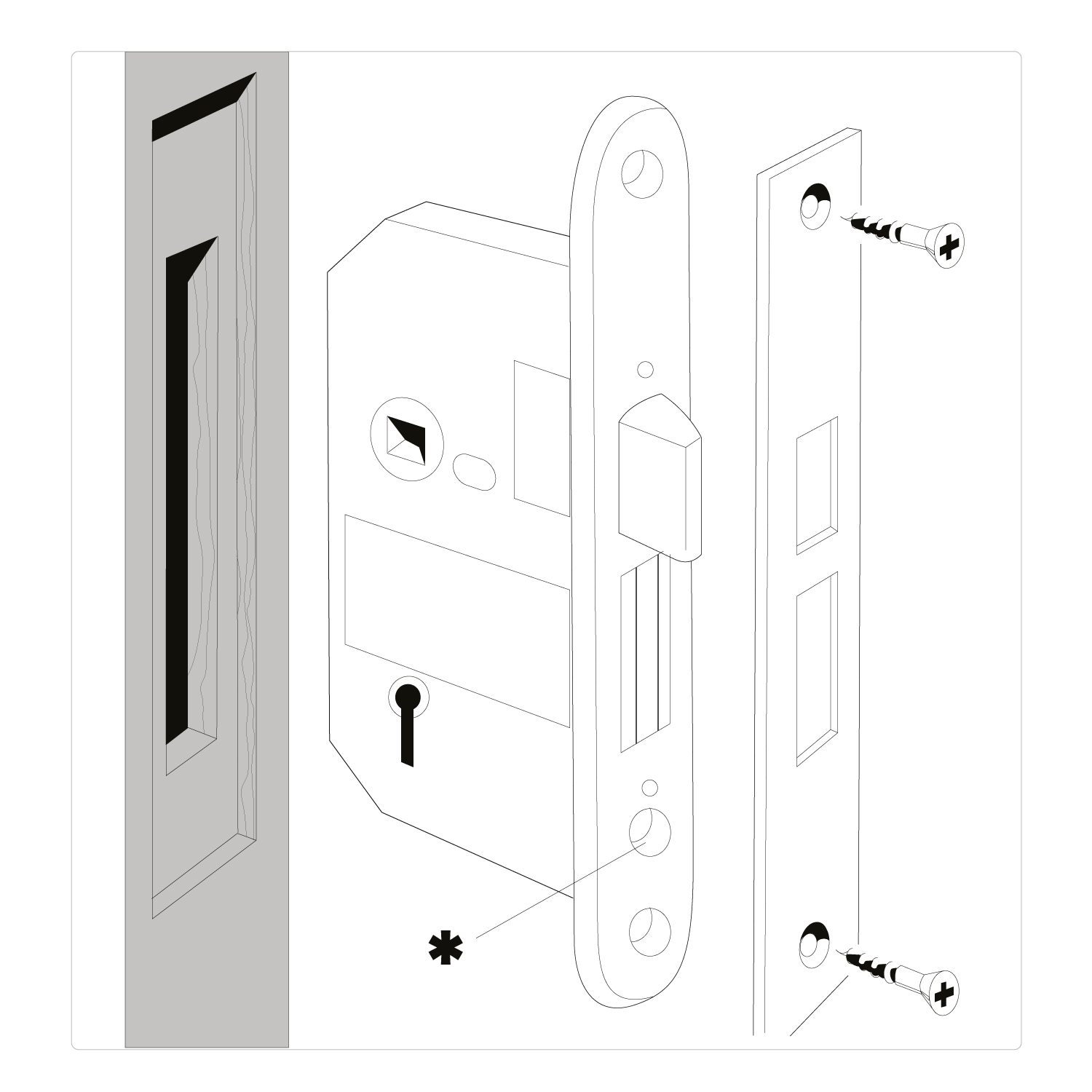
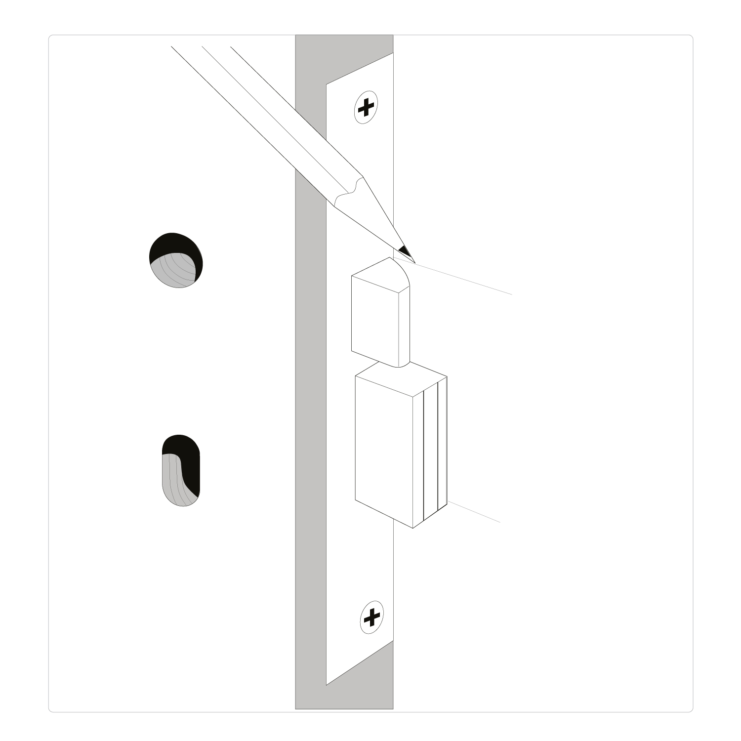
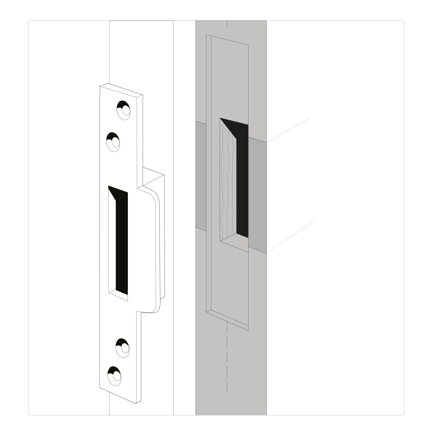
Please note: when fitting a Euro sashlock, insert the cylinder retaining screw through the lock before fitting the faceplate in position.
With faceplate in position, secure the lock into the door with screws provided. Then fit escutcheons and/or door handles with the spindle cut to suit. Test for easy operation.
To fit the box keep/ striker, with the door open and the bolt in the locked position, close the door gently against the door frame.
Mark the positions of the bottom of the bolt and the top of the latch bolt. Between these two lines mark a central vertical line (dotted line) on the door frame.
Hold the box striker on the door frame, ensuring the box section is in line with previous markings.
On the door frame draw around the box section of the striker.
Along the vertical line, drill a series of overlapping holes to the box striker depth.
Re-hold the box striker to the door frame and draw around the edge. Remove the box striker and chisel out, so the box striker sits flush within the door frame.
Secure the box striker using the screws supplied in the central or elongated holes only.
Test the complete lock for working operation, and adjust the position of the box striker if required.
When aligned correctly, fit the two remaining screws.
Terminology
Sashlock
A lock mechanism incorporating both a latch and deadbolt feature. Sashlocks can be key operated with a lever mechanism or cylinder operated and can incorporate thumbturns for keyless egress applications. Typically used with a lever handle set.
Deadlock
A lock mechanism incorporating a deadbolt only. Deadlocks can be operated with a lever mechanism or cylinder operated and can incorporate thumbturns for keyless egress applications.
Latch
A self-engaging element of the lock that secures the door when engaged with the keep, and can be released by hand. Latches can be deadlocked so that when the lock mechanism is engaged, the latch cannot be withdrawn.
Deadbolt
A bolt that is operated in both directions by a key, handle or thumbturn.
Differ (effective differ)
The difference between locks of similar design, achieved by the levers, allows each lock to be operated by its own key.
Forend (faceplate)
The element of the lock case through which the lock is fixed to the door, and through which the latch and or deadbolt pass. Faceplates may have a square or round end.
Spindle
The square section drive bar, usually 8mm in width that is positioned through the drive of the lock and locates into the handle set levers, or knobs. Operating the lever rotates the spindle, which in turn operates the drive (follower) of the lock. The required length of the spindle is dependent upon the thickness of the intended door and the depth of the receiving element of the handle lever.
Centres
The vertical dimension between the lock spindle and the centre of the keyway of the gearbox. Centres can vary between lock systems, though the ERA range has a standard of 57mm. Understanding the lock centre dimension is critical for the specification of the correct handle.
Rebate
A rectangular recess along the edge of a frame to receive the corresponding door leaf. Rebates are also machined into the meeting rails of double doors to provide closing faces for the corresponding leaves. Rebate conversion kits are required for door locks and keep, fitted into rebated edges of timber doors.
Backsets
A backset is the distance between the lock keyhole and the outer edge of the lock.
Keeps/ Striker
The element of the lock system that is fitted to the fixed portion of the door frame, into which the moving part of the lock (e.g. bolt) engages when in the locked position.
Need further help?
If you have any questions, please contact the ERA Expert team who would be happy to assist. Or for further details ERA has a broad range of mortice lock solutions to suit the majority of applications. For more information visit eraeverywhere.com
